Run a Wire

Coax Cable

New Construction

Run an RG6 cable terminated with an BNC connector from a central location to coax jack on the wall of the desired room. Be very careful when pulling the wires. Do not stretch them or make them turn sharp corners. The wires should not be taught after installation because they can be stretched over time as the house settles.

Existing Home

Unfortunately, the answer is still to run the RG6 coax wire. If you cannot run it through your attic or basement, then you may have to run it outside your house and come in through a wall.


Ethernet Cable

New Construction

Run a Cat 5E wire terminated with an RJ-45 connector from a central location to an Ethernet jack on the wall at the location your want to network. Us  the T568A wiring scheme of the EIA/TIA-568 cabling standard and to terminate the wires. Be very careful when pulling the wires. Do not stretch them or make them turn sharp corners. The wires should not be taught after installation because they can be stretched over time as the house settles. For more on how to terminate Ethernet cables click here.

The Ethernet standard specifies a maximum distance of 100 meters (including all attached cables), but you may get better results staying within 100 feet. For longer runs, add a LAN switch in the middle to make two or more shorter runs.

At the central location, plug the wires directly into a LAN switch. Avoid extra connections such as punch down blocks as they may (slightly) decrease the integrity of the signal .

After installing the wires and connectors  the following test should be run:

  • Wire map test to show that the wires have been connected properly.

  • Length test to show how long the apparent length of wire is.

  • Attenuation test at 100 MHz where the attenuation must not exceed 22dB in any pair.

Existing Home

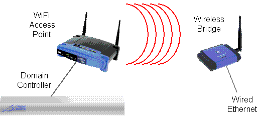
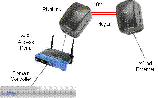
If you can run a wire, then this is the best approach. If not, you have two options: use WiFi (a.k.a. Wireless Ethernet) or HomePlug (a.k.a. Ethernet over power line). Of the two, WiFi is better known and you may already be using it for you laptop. However, HomePlug may be the better choice if you have a long distance to run.


WiFi Extension

Use a "Wireless Bridge" such as the Linksys  WET11 to convert WiFi into wired Ethernet. All it needs is a 110V socket to plug into.


HomePlug Extension

Use a HomePlug to Ethernet adapter such as the Asoka PlugLink Ethernet Wall Mount to convert Ethernet to HomePlug and a second one to convert HomePlug back to wired Ethernet. Just plug each of them into a 110V socket. Make sure to get both of them from the same vendor as the software setup is different for each vendor.


IR Transmitter Wire

New Construction
Domain 3000

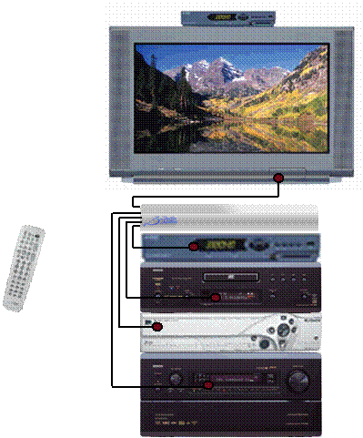
Connect an IR transmitter such as the Xantech 282M or 283M mouse emitter from one of the IR output ports on the back of the Domain 3000 or Global Cache GC-100 controller to each AV component to be controlled. The IR emitter plugs directly into the Domain 3000 and GC-100.


Existing Home

Wiring an existing home is the same as wiring new construction. The one exception may be that you would have to Run an Ethernet Cable to the Global Cache via WiFi or HomePlug


Low Voltage Power Wire

New Construction

Pull an 18-2 stranded wire from a central location to the room in which the low voltage power is needed. Power multiple of these circuits with a quality power supply like those made by Altronix such as the AX-SMP10C12X which provides 10A at +12V in a UL listed enclosure.

Existing Home

Pull the same low voltage wire as is listed in New Construction through your attic or basement, if possible. If not, then plut a power supply into a local 110V socket.


Power Status Wire

New Construction
Domain 3000
Power Status via Video Sync

Connect a composite video cable from a spare composite output signal of the AV component to one of the four Video Sync input ports on the back of the Domain 3000. These ports are specifically designed to accept a composite video cable.

If the AV component does not have a spare composite output port, then put a passive composite video splitter on one of the ports that is already in use.

Power Status via a Current Sensor

Plug the AV component into a current sensor such as the Xantech CSM1 Current Sensor, and connect a wire from the current sensor to one of the four digital input on the back of the Domain 3000.

The pin out of the Domain 3000 is compatible with the CSM1.


Power Status via a Light Sensor

A light sensor such as the Niles Audio Light Sensor is used to detect the light on the front panel display of an AV component when the component is turned on. This assumes the display turns off when the component is turned off. The light sensor is pasted onto the front of the display just like a IR mouse emitter would be. The light sensor goes to its own control unit which then plugs into one of the four digital inputs on the back of the Domain 3000.

Please see the Domain 3000 Back Panel for the necessary pin out.

Global Cache
Power Status via Video Sync

Connect a Global Cache GC-SV1 Video Out Sensor cable from a spare composite output signal of the AV component to one of the digital input ports on the back of the Global Cache GC-100. The GC-SV1 includes a passive composite video splitter so that it can be used on one of the ports that is already in use.

Power Status via a Current Sensor

Plug the AV component in the Xantech CSM1 Current Sensor, and plug it into the Xantech CSM1-77 connecting block so that the proper voltage can be supplied to the Xantech CSM1 Current Sensor. Connect a wire from the connecting block to one of the digital input on the back of the Global Cache GC-100.

You will need to follow the pin out of the GC-100 which can be found here.

Power Status via a Light Sensor

A light sensor such as the Niles Audio Light Sensor is used to detect the light on the front panel display of an AV component when the component is turned on. This assumes the display turns off when the component is turned off. The light sensor is pasted onto the front of the display just like a IR mouse emitter would be. The light sensor goes to its own control unit which then plugs into one of the digital input on the back of the GC-100 .

You will need to follow the pin out of the GC-100 which can be found here.

Existing Home

Wiring an existing home is the same as wiring new construction. The one exception may be that you would have to Run an Ethernet Cable to the Global Cache via WiFi or HomePlug.


Relay Control Wire

New Construction

Connect a 22-2 solid or stranded wire for applications that just require Normally Open (Form A) or Normally Closed (Form B) relays or connect a 22-4 solid or stranded wire for applications that require both Normally Open and Normally Closed (Form C) relays from the Domain Controller to the device to be controlled. If you run out of relays on the Domain Controller, you can add additional relays from the following vendors:


Existing Home

If possible, run a 22-2 or 22-4 wire just like you would in wiring new construction. If that is not possible, then you will have to Run an Ethernet Cable via WiFi or HomePlug to a Global Cache GC-11 and run the 22-2 or 22-4 wire from it to the device to be controlled. Note that the GC-100 will need a power outlet, too.


RS-232 Cable

New Construction

Run a Cat-5E cable from the Domain Controller to the device to be controlled. Only 3 wires of the Cat-5E cable will be used (normally), but it is preferable to use this cable so that if there is a problem with one of the wires or if you need to convert the signal to RS-422 for greater distances, a cable that has more wire is available. This also means that you can upgrade the signal to Ethernet if you have to at some point in the future. Terminate the cable with the appropriate DB-9, DB-25, RJ-45, RF-11 or Phoenix connector as necessary.

Existing Home

If you can pull a Cat-5E cable through the attic or basement, this is the preferable method. If not, then Run an Ethernet Cable via WiFi or HomePlug and connect it to a Global Cache GC-100. That box will then supply the necessary RS-232 port.


RS-422 Cable

The specification for RS-232 is a maximum of 50 feet where as the specification for RS-422 is thousands of feet because the latter uses differential signals. Other than the physical layer signaling standard, for most applications, the two are the same and use the same software protocol (the actual specification allows for multiple nodes, but RS-485 is typically used for this application).

New Construction

Connect a short serial cable from the Domain Controller to a B&B Electronics 485OT9L RS-232 to RS-422 and RS-485 Converter. Run a Cat-5E cable from the RS-232 to RS-422 and RS-485 Converter to the device to be controlled. If necessary, convert the signal back to RS-232 using a second RS-232 to RS-422 and RS-485 Converter.

There are a number of other RS-232 to RS-422 converters on the market. It is likely that many of them will also work. However, we have not tested them. We like the B&B Electronics 485OT9L because it is optically isolated and can also be used to convert RS-232 to RS-485 (so you only have one part to buy for both applications).

Existing Home

If you can pull a Cat-5E cable through the attic or basement, this is the preferable method. If not, then Run an Ethernet Cable via WiFi or HomePlug and connect it to a Global Cache GC-100. Connect the RS-232 port of the Global Cache GC-100 to the B&B Electronics 485OT9L RS-232 to RS-422 and RS-485 Converter.


RS-485 Cable

RS-232 was designed to connect one device to one other device, where as, typically, RS-485 connects one master device to one or more slave devices.

New Construction
Domain 3000

Connect a short serial cable from the Domain 3000 or Global Cache GC-100 to a B&B Electronics 485OT9L RS-232 to RS-422 and RS-485 Converter. Run a Cat-5E cable from the RS-232 to RS-422 and RS-485 Converter to the devices to be controlled. Note that you may need a terminating resistor at the end of the cable. Do not connect devices from multiple manufacturers to the same RS-485 cable as it is unlikely that they will interoperate.

Existing Home

If you can pull a Cat-5E cable through the attic or basement, this is the preferable method. If not, then Run an Ethernet Cable via WiFi or HomePlug and connect it to a Global Cache GC-100. Connect the RS-232 port of the Global Cache GC-100 to the B&B Electronics 485OT9L RS-232 to RS-422 and RS-485 Converter.