The Domain 3000 has 25 I/O ports plus a connector for an external power supply (included) and an LED to indicate that the power is on. Typically, it is placed on a shelf or equipment rack with the AV equipment to make it easy to add the wires.
See below for more information on:
|
|
|
|
With the introduction of the "Powered RF Antenna", the BNC port is no longer used (previously, it was used for a conventional passive antenna).
Connect the +5V 10W power supply to this plug.
In this release, the USB port is not used (and does not count as one of the 25 ports).
The 100 Fast Ethernet port is located on the back of the Domain 3000. Use Cat 5E wire terminated with an RJ-45 connector (standard Ethernet cable) to connect the Domain 3000 to a 10/100 Ethernet switch. Note, it must be connected to a 100 Mbps Ethernet port. It will not work when connected to a 10 Mbps Ethernet switch. Alternatively, you can connect it directly to your PC using a cross over cable.
A compact flash port is on the lower left portion of the back panel. The flash card contains the Ubiquity applications, house configuration files and operating system for the Domain 3000. It should only be removed by trained technicians. Damage or changes to the compact flash card or its contents will adversely affect the operation of the Domain 3000. Note that the contents of the flash card cannot be read by your PC.
. If you need to replace it, make sure to power down the Domain 3000 before removing or inserting the compact flash.
There are two RS-232 serial ports that run at baud rates of up to 115.2 Kbps. These ports do not support RTS/CTS nor XON/XOFF. If your application requires support of RTS/CTS the easiest thing to do is loop back RTS to CTS by wiring those signals to each other in the serial connector of the device your are connecting to the system. We do not know of any applications where this does not work. However, another solution is to use a Lantronix USD 100 or 200 Ethernet to Serial converter which supports RTS/CTS functionality.
|
The Domain 3000 serial ports have the standard DB-9 male DCE pin out of:
This means that if your PC can talk to a device over a serial cable, then you can unplug the serial cable from your PC and plug it into the Domain 3000. |
|
There are 8 independent IR outputs. They are typically wired to IR emitter such as the Xantech Mouse Emitters 282M and 283M.
|
Connector Signals |
Soldering Wires to the Connector |
There are 4Video Sync RCA Input Ports. They are typically wired directly from the composite video output of an AV component. Please disregard the fact that two of them are white and two are yellow. All are video sync ports.
The "Powered RF Antenna" plugs into port #2 of the "Digital Inputs" (see below), The antenna can be extended with a simple 3-wire stereo jack extension cable. We have tested the extension cable using a 500 foot spool of 28 gauge wire.
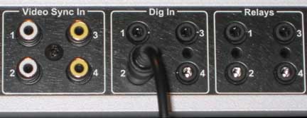
There are 3 Digital Inputs (after using port #2 for the Powered RF Antenna). They are typically wired from a sensor that indicates the Power Status state of an AV component. Note that the pin out is designed to correspond exactly with the Xantech CSM1 Current Sensor - including the ability to supply power to it.. The signals are:
Tip is +12V out from the Domain 3000 to an external device
Ring is the digital input from an external device
Sleeve is the ground of the Domain 3000
. .
|
Connector Signals |
Soldering Wires to the Connector |
There are 4 "Form C" relays on the right hand side of the back of the Domain 3000 (but to the left of the +12V triggers).
Max. switching power: 60 W, 125 VA
Max. switching voltage: 220 V DC, 125 V AC
Max. current: 2A at 30VDC or 0.5A at 125AC
|
Connector Signals |
Soldering Wires to the Connector |
There are two +12V Triggers that can supply up to 100mA of combined total output current (either one alone can supply up to 100mA, but both combined cannot exceed 100mA). The plugs are shown as stereo type plugs, but mono plugs can also be used (in which case the "Ring" is not used).
|
Connector Signals |
Soldering Wires to the Connector |