RS-485 Connection
Connect one of the RS-232 serial ports of the Domain Controller to a B&B Electronics RS-232 Converter. Set the dip switches of the B&B as discussed in Wire the B&B for the KPG8.
Multiple keypads can be connected to the same RS-485 serial interface of the B&B.
The recommended wiring is Cat 5E twisted pair cable with a maximum recommended cable length to the controller of 4000 ft.
The communication settings for the Domain Controller RS-232 port are: 9600 baud, 8 data bits, 1 stop bit, no parity and no flow control.
The . The 12V DC power supply in the Domain 5000 cannot supply enough current to run the keypad.
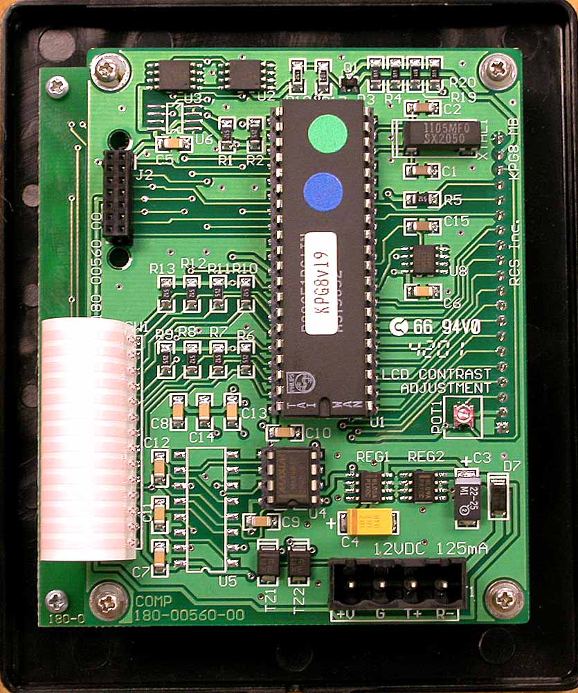
The Picture at the right shows the circuit board on the back of the keypad with connector shown at the bottom right
Programming the RCS Keypad
NETWORK PROTOCOL
The KPG8 uses the CommStar RS485 ASCII protocol. It is fully supported by RCS Network Control Units. Communications Settings: Half duplex, 9600 baud, 8 data bits, 1 stop bit, no parity and no flow control.
WIRING
Recommended wiring is Cat 5 twisted pair cable. Max cable length to CommStar Hub is 4000ft. Other wiring topologies subject to their network requirements.
KEYPAD SETUP MODE
To enter setup mode, press and hold the top button on the keypad for 5 seconds until the display switches to the setup screen. From the setup screen you can verify Firmware version number, change network address, screen timeouts, default menu, time format, and other modes. To exit the setup screen, press the bottom button labeled “Main” to return to the default main menu.
FIRMWARE VERSION
The keypad firmware version number is displayed in the setup screen.
KEYPAD ADDRESSING
The keypad network address is displayed and set from the setup screen. Address range is 1 to 124. Default is address 1.
DEFAULT SCREEN NUMBER
From the setup screen, you can set the default screen menu number that the keypad will default to after the screen timeout period has expired. This must be a menu defined and downloaded in the keypad.
SCREEN TIMEOUT
From the setup screen, you can set the screen timeout period in seconds. Time out range is 0 to 255 seconds. After this time period expires, the keypad will switch to the default screen menu number set above. If time out period is set to “0” seconds, the screen will not time out and will stay active.
BACKLIGHT TIMEOUT
From the setup screen, you can set the backlight timeout period in seconds. Time out range is 0 to 255 seconds. After this time period expires, the backlight will turn off. If the time out period is set to “0” seconds, the backlight will not timeout and will stay on constantly.
TIME FORMAT
From the setup screen, you can set the time format displayed on the screen from 12 hour to 24 hour format.
Configuring the Ubiquity Software
One of the best parts of the RCS keypad is the LCD text display that supports multiple pages of text (as shown at the right).
The text can be configured by the Ubiquity software via the Text tab of the "Add a Keypad" menu. Please see Configuring an RCS Keypad.
Note that the two columns of button correspond to the two sides of the rocker buttons on the RCS keypad. Given that there are only 10 characters of text per line of the display, you may want to have both buttons of the rocker do the same thing (as shown in the example).
Note also that the bottom buttons (labeled "Thermostat") take you to the Thermostat page of the keypad. On this page the LCD display will show different commands and the button will perform different actions - all configured in the Design Module.
Click OK to upload the text to the RCS keypad. This may take 30 to 60 seconds.
Hyper Terminal
You can use Hyper Terminal to test the connection. Disconnect the serial cable from the Domain Controller and connect that end to your PC.
Open Hyper Terminal: 9600 baud, 8 data bits, 1 stop bit, no parity and no flow control. In the properties ASCII set up, turn on sending line feeds.
Send to the RCS Keypad:
The format for RCS keypads for writing menu items
to go to a different menu when keypad is pressed is:
!TPxxMmmiiZqqrrssssssssssssss (followed by a return or \r)
where xx = hexadecimal keypad number (starts with 01, everything else is zero-based),
where mm = hexadecimal menu or page number (keypad menu or page)
where ii = hexadecimal menu item (row)
where Z is 1 for left button, and 2 for right button
where qq = button control (01 is goto another menu/page)
where rr is hexadecimal menu number to go to
in theory we should need anything for sssssss, but in
reality we need 6+ bytes (RCS bug?), so just add
"M" + <2 byte hexadecimal hexadecimal menu/page (zero-based)> +
"B" + <2 byte hexadecimal button ID (zero-based)>
Receive from the Keypad:
// things can come back to us like this: !TPnnQx0 for nothing pressed and
// !TPnnQxMessage for a "real" message, where 'x' is some strange control
// character and nn is the keypad ID number and everything has 2 characters
// of control characters at the end