|
o |
Connect
your PC directly to the Domain 3000 with an Ethernet crossover cable
Remove the Ethernet crossover cable (the yellow
one with red tape near the connectors) from the box. Note that this is
not a regular Ethernet cable and should not be used for any purpose other
than connecting your PC directly to the Domain 3000.
Connect your PC directly to the Domain 3000
via the Ethernet crossover cable.
Connect the power supply to the Domain 3000.
Give the Domain 3000 5 minutes to boot up
while you do the next set of steps.
|
|
|
o |
Within 1 minute, the Ethernet port should
be up and running. The upper left LED must be orange - indicating that
the Domain Controller is communicating at 100 Mbps. If it is not orange,
the Domain Controller is either not communicating or is communicating
at 10 Mbps. Neither will work. |
|
|
o |
Give
Your PC an Alternate IP address of 172.16.16.117
Configure your PC with an "Alternate
IP address" of 172.16.16.117 so that your PC comes up on the same
network as the default address of the Domain 3000.
Do this by going to your desktop and right
clicking on "My Network Places" and selecting "Properties".
|
|
|
o |
The "Network Connections" menu will
pop up.
In the "Network Connections" menu
make sure your wireless network is disabled (right click it and select
Disable, if necessary).
Then, in the same "Network Connections"
menu, right click on the Ethernet port that is plugged into the Domain
3000 and select Properties.
|
|
|
o |
The "Local Area Connection Properties"
menu will pop up.
On the "Local Area Connection Properties"
menu, select "Internet Protocol (TCP/IP)" and click the "Properties"
button. |
|
|
o |
General
Configuration tab
On the "Internet Protocol (TCP/IP)"
menu, typically,
it will try to "Obtain an IP address automatically" and look
like the menu at the right. If this is the case you can proceed to the next step below.
|
|
|
|
If, however, "Use the following IP address"
is selected (as shown at the right) and if the "IP address"
is not in the 172.16.x.x network, then jot down all the information on
this page and change the information as follows:
IP address: 172.16.16.117
Subnet mask: 255.255.0.0
Default gateway: 172.16.0.1
the rest will not matter.
If your PC was on the 192.168.x.x network
or the 10..x.x.x or any other network than the 172.16.x.x network, then
it is likely that you will want to change
the IP address of the Domain 3000. You can do this now and then return
to this spot, and change your setting back to the way there were.
Click OK to this menu and the other menus
and go on to opening "Find My Destiny". |
|
|
o |
Alternate
Configuration tab
On the "Internet Protocol (TCP/IP)"
menu, select
the "Alternate Configuration" tab.
Click "User configured"
Enter:
IP address: 172.16.16.117
Subnet mask: 255.255.0.0
Default gateway: 172.16.0.1
as shown at the right.
Click OK to this menu. |
|
|
o |
Adjust
Norton Internet Security
If you have Norton
"Internet Security" on your PC, please enable the Ubiquity application
by doing the following:
Right
click the Norton Internet Security icon (located in your system tray at
the bottom right or your screen). Select
"Open Norton Internet Security". Choose
Personal Firewall. Click
the "Configure" button. Select
the "Program" tab. Scroll
through the list of applications to find "LaunchAnywhere GUI". Click
on the "Block All" to the right of that application and change
it to "Permit All" Click OK and exit Norton
Internet Security.
|
|
o |
Open Find
My Destiny (PC directly to the Domain 3000 with an Ethernet crossover
cable)
From the Microsoft Windows "Start"
button, select "All Programs", "Destiny Networks",
"Ubiquity3.1", "Find My Destiny".
The "Find My Destiny" application
will find the Domain 3000 and assist you in troubleshooting any problems
you may run into.
As shown in the screen shot below, the "Find
My Destiny" application has three sections.
The middle section will tell you information
about your PC and its connectivity to the network. It will analyze your
PC to make sure it is running the Microsoft Windows XP operating system,
Microsoft Internet Explorer 6.0 and the Adobe Scalar Vector Graphics (SVG)
viewer (which was installed with our software). These should all have
a green "OK" after them. It will also check your Ethernet network
interface card. If you are using the Ethernet crossover cable to connect
your PC to the Domain 3000, then you should see an IP address of 172.16.16.117
and this test should also have a green "OK" after it. Finally,
it will test your Internet connection. Note that Internet connectivity
is not necessary for using Destiny Networks' products. If you are using
the Ethernet crossover cable to connect your PC to the Domain 3000, then
this test will show a red "Not Available". Later, if you connect
the Domain 3000 to your home network, this information can be useful to
see if your network is behaving properly.
The right section of the application will
show you information about the Domain Controller and its connection to
the network. when the name of a Domain 3000 appears in the box on the
upper right, click on the name to select it (for
example, the name "d3k_E11B" was clicked on in the example below).
The name of the Domain 3000 consists of the "d3k" abbreviation
of the product plus the last 4 bytes of the MAC address of your particular
unit. The MAC address is written on the back of the Domain 3000. You must
click on the name before proceeding to the next step. If the name does
not appear, make sure your PC is connected to the Domain 3000 via the
special Ethernet crossover cable supplied in the box and that the Domain
3000 power supply is plugged in.
Soon after clicking on the name of the Domain
3000, information about the Domain 3000 will appear below the box (you
may have to scroll the window to see it). You will see information about
the Domain 3000's network connectivity and version of software. Below
those two things, you will see the boot up status of the Domain 3000.
In the example below the status is "Browser interface up and running".
This is the final step and it means that the Domain 3000 is now fully
up and running. If it says something else, please wait for the Domain
3000 to finish booting up.
Since you are using the crossover Ethernet
cable, then you will get the warning shown below about the missing DHCP
server. You can disregard the warning because you are connected directly
to your PC, and, therefore, are not using a DHCP server.
|
|
o |
Now, skip over the other method
of using a Local Area Network to connect to the Domain 3000 and go to
opening the Design Module.
|
The Schematic
View
You will open up the schematic of the AV equipment
in the room. The schematic supports graphical entry of interconnects -
as we will see shortly.
Before any equipment has been added to the
room, you will just have the Domain Controller and any additional control
ports that have been added to the project (e.g., Global Cache, Lantronix,
etc). In the example below, you see the control ports of the Domain 3000.
At the top of the menu, you see the "File"
dropdown menu. Use this to print a copy
of the schematic.
There are 4 buttons at the bottom of the menu.
Here's what they do.
Click the "Whole
House" button to see all of the AV components throughout the house.
Use this view to connect AV and control wires to distributed audio and
video components. Once you are in the Whole House view, you
will not be able to add AV components to the rooms - just wire
together existing components. If you only have one room of entertainment
equipment in your house, then there is no need to use this button. Click the "Add
Component" button to add the AV components to this
room of your project. Click the "Preferences"
button to modify the default set up created by the software for selecting
sources and their paths to displays and speakers. For more information,
please see AV Preferences. Click the "Done"
button when you are finished making changes. The changes you make happen
immediately. Therefore, the Done button just closes the Schematic window.
|
|
|
Add Component
Menu
The first step is to add all of the AV components
to the room.
Click the "Add Component" button
on the menu above.
You will get the menu below.
Choose between the "Destiny
Library" of AV components (which consists of Device Description Files
supplied by Destiny Networks) or the "User Library" (which contains
Device Description Files created by you). The User Library contains all
the files create by you - whether they were created from scratch or as
a result of modifying a file in the Destiny Library. If
you do not see the component you are looking for, check that you have
selected the correct library. Choose the "Type"
of AV component you plan to add to the project from the dropdown box.
Note that the PVR "Type" includes Cable
Set Top Boxes and Satellite receivers that have an integral PVR
function (e.g., a TiVo function). Also, AV Surround Receivers include
Stereo receivers. AV switches are of the "Switch" type. Choose the "Manufacturer". And the "Model" Each model may have
one or more files associated with it. Usually, the file name gives some
indication to the completeness or the AV component or tells you how the
AV component is controlled. For example, the one below is controlled via
RS-232, but probably does not have IR codes. The "Name"
is the unique name for this component in the house. By default, it will
begin with the name of the room and end with the component's "Type".
You can almost always leave the name as is. This name will appear in "Check
My Destiny" and also in the
Advanced menu of the Entertainment Browser GUI menu. The "Name to be
Displayed" is the name that will appear on the button of the "Entertainment
Browser GUI" (the nice looking entertainment menu). This is the button
used to select this component as a source (note that only sources will
have names that are displayed, but the text field is available for all
devices to allow for "internal components" - as we will see
below with the internal AM/FM tuner of the AV surround receiver).
|
|
|
If the device you want
to add to your project is not in either the "Destiny Library"
nor your "User Library", then you can click the "Create
New Component" button to bring up the Device Description Wizard.
This will add the new component to your "User
Library". If you have multiple
AV components to add to the project, then click the "Add & Continue"
button. It will add the selected AV component and keep this menu open
to add more AV components to the project. If this is the last
AV component you want to add to the project at this time, then click the
"Add" button. It will Add the AV component you have chosen and
close this menu. If you have finished
adding AV components to this room of the project, click cancel to close
this menu. All components that were added previously will remain in the
project. This button just closes the menu.
|
Add
the Samsung DVD-HD941 DVD player
Select the "Destiny Library"
Press the "Tab" key twice to get
to the"Type" field and use the dropdown menu to select "DVD"
(or press the "D" key with this field highlighted).
For "Manufacturer" select "Samsung"
or substitute the manufacturer's name of the DVD player you actually intend
to use.
For "Model" select "DVD-HD941".
You can use the defaults for the rest.
Note that this device uses the play command
to create a discrete "Power On" command, but it does not have
a discrete "Power Off" command.
Click "Add & Continue"
|
If your AV component does not exist in the
library, please check the AV
components on our web site to see if the component has been added
more recently than those shipped with this software release. If not, please
proceed to the Device
Description Wizard (DDW) to create the Device Description File for
a new component. |
|
A new component will appear on the schematic
and the "Add Component in Theater" menu will still be available
for adding additional components.
The DVD player will have a red top banner
- indicating that it has one or more errors associated with it. This error
reporting capability is called AV AWARE (Audio/Video Always Watching And
Reporting Errors).
Click on the "err" (on the right)
to see the errors. At this point, the pop up error menu would report the
following.
Clicking "ignore" will cause AV
AWARE to ignore this error.
Clicking "more" will give you the
long version of the error message and point you to possible solutions.
|
|
|
Add
the DirecTV HD Satellite Receiver / PVR
For "Type" use the dropdown menu
to select "PVR" (or press the "P" key one or more
times with this field highlighted).
For "Manufacturer" select "DirecTV".
For "Model" select "HD DVR".
You can use the defaults for the rest.
Click "Add & Continue" |
|
Add
the Denon AVR-3805 Surround Receiver
Select the AV Surround Receiver "Type",
Denon for the "Manufacturer",
And the AVR-3805 "Model".
Change the "Name to be Displayed"
to "AM/FM" because this component has an AM/FM receiver as an
"internal component". Thus, the source button for the AM/FM
turner will read "AM/FM Tuner".
Click "Add & Continue"
|
|
Add
the Sharp XYZ 9000 Projector TV
Select the TV "Type",
Sharp for the "Manufacturer",
And the XYZ 9000 "Model".
You can use the defaults for the rest.
Click "Add & Continue" |
|
Add
your favorite 5.1 surround sound speakers
Select the Speaker "Type",
Generic for the "Manufacturer",
And the Surround 5.1 speakers "Model".
You can use the defaults for the rest.
Click "Add" because we are finished
adding components.
Note that if you clicked "Add
& Continue" instead of "Add", then you have added the
last AV component and you can click "Done" to get out of this
menu.
|
|
Schematic
Menu Layout
You will end up with the schematic shown below.
It has the following format:
The 1st column contains
the Domain Controller. The 2nd column contains
AV sources. The 3rd column contains
AV surround receivers and video processors. The 4th column contains
displays and speakers.
For each
component:
The top line displays
the name of the AV component. If you click on the name, the Info
Menu will pop up - providing you more information about the AV component.
The small letter "i" to the right of the name is there to remind
you that you can get "information" about the AV component by
clicking here (or anywhere on the name). If you want to Delete
the AV component from this project, click on the "x" at the
far right of this line. The top set of ports
will be outputs and they will be "right justified". The 2nd set of ports
will be inputs and they will be "left justified" The 3rd set of ports
will be one or more control ports (e.g. "IR Control" and/or
"Serial Control"). The last port will be
"Power Sync" port and it will be written as one of:
"Power Sync
(not needed)" if the AV component does have discrete power commands
"Power Sync
(recommended)" if the AV component does not have discrete power commands "Power Sync
(high)" if the port is wired to a Video Sync input on the Domain
3000
At this point, you have added the components.
Now it is time to wire the components together in software - just like
they are physically wired.
Color
key to Wire Types
As you begin adding wires, you will notice
that they have a color associated with them based on their wire type.
|
Color |
Wire |
|
Blue |
Video |
|
Green |
Audio |
|
Red |
IR Control |
|
Yellow |
Power Sense |
|
Silver |
Serial |
|
|
|
Wire them together in software just
like they are physically wired
After adding the AV components to the room,
the only other step is to wire them together. There are two ways to do
this. The simplest is to use "Auto Wire".
"Auto Wire" will automatically add
wires to the AV components on the Schematic view with the goal of giving
you the highest quality Audio and Video experience based on the wire types
you choose to use. It will also connect IR control wires from the Domain
Controller to each of the AV components to create a wiring schematic of
the entertainment system. Finally, it will automatically generate the
control program for the Domain Controller so that multiple brands of RF
remote controls and multiple types of web tablets can control your entertainment
system.
Auto Wire will give you control over the types
of wire it will use. If you would like more information on wire types,
please see Wires for Video and Wires for Audio.
Auto Wire will not wire the following device
types: Amplifiers, Splitters, and Video Processors. Also, it will not
wire distributed AV to multiple rooms. But it will usually do a nice job
on theaters. Auto Wire will not wire 5 line level speaker "pre-out"
wires. If this is from a DVD player, you will want to add these wires
to get SACD audio. However, the DVD will want to use digital or line level
stereo out, so that is what Auto Wire will wire.
Auto Wire will assign
IR and serial ports in the order in which they were added to the schematic
view. For example, if the TV is added 1st and the AV surround receiver
2nd, then the TV will be assigned to IR Port 1 of the Domain Controller
and the AV surround receiver will be assigned to IR Port 2 of the Domain
Controller
Note that it is a good
idea to save the project before using Auto Wire. That way you can
revert back to the unwired state if you do not like the wires that Auto
Wire adds (but this is pretty rare).
Click the "Auto Wire" button at
the bottom of the schematic view.
|
Auto Wire
You
will get a pop up menu that looks something like the one at the right.
It will offer the super set of all wire types supported by two or more
of the AV components on the schematic. They are listed in quality order
with the highest quality on top.
Auto
Wire will only wire the highest quality signals needed to get all sources
to the display and speakers in the room. For example, if Auto Wire can
complete a path with Component video, it will not wire S-Video.
Note that the "Line
5.1 Speakers" output from a DVD player to an AV surround receiver
will be wired, but that those wires do not count as the "audio"
wire. That is, the 5.1 can be used for SACD, but an additional audio wire
will be added for playing a conventional video DVD. In the example above
using the selections at the right, that wire will be "Line stereo
RCA" (because the PVR does not have coax or optical digital out and
the AV surround receiver does not have HDMI in).
Note also that the line
subwoofer does not count as the audio wire, either. Again, it will be
added for documentation purposes, but so will speaker wires.
De-select
any types that you do not want to use. Auto Wire will not use them.
Click OK.
|
|
|
After clicking OK, you may get an important
warning saying that one or more "Assignable Inputs" were assigned.
Note that this will require you to do the assignment
in the AV surround receiver. The software cannot do that assignment
for you.
Make a note of the assignments (perhaps using
a screen capture and print program like PrintKey2000).
Then click OK.
|
|
After clicking OK you will see a wired entertainment
system. Note that the assignable inputs of the AV surround receiver are
colored blue to remind you that you have to assign them on the AV surround
receiver.
|
|
Note that errors still exist. If you click
on the "err" of both components, you will get the following.
After adding Power Sync wires (as described
below), the errors will go away and you will have a working program.
|
Add a Wire
If you do not use Auto Wire, or if you want
to change the wires after using Auto Wire, then you will want to do the
following.
Let's start at the far right. Click on the
port at the top of the "Living room TV". It is named "Cpt
1: Component". That port will turn blue and all compatible output
ports that do not have an existing connection will turn green. In the
example below, the blue port on the upper right was clicked (turning it
blue) and the 3 available component output ports turned green.
|
|
|
|
Click on the green port belonging to the Denon
AV surround receiver. The colors will disappear from the ports and a line
will be drawn between the two ports that were selected.
Now, the Ubiquity software running in the
Domain Controller now knows that a path exists from the Component output
of the Denon AV surround receiver to the "Cpt 1" input connector
group of the Sharp projector TV and that the connection is a component
video signal.
|
|
Orange-colored
Ports are Already Connected
When you click an unused port, you will often
see some ports highlighted orange instead of blue. These ports are compatible
ports, but they already have a connection going to them. If you choose
to wire to an orange port, you will be told that your are deleting an
existing connection.
To see the orange highlighting, click on the
2nd port of the Theater TV - the one labeled "Cpt 2: Component"
(as shown below).
De-Select
all Ports
Click anywhere on the gray part of the page
and outside of the AV components to de-select the port.
|
|
|
Control
the Sharp Projector TV via RS-232
Click on the serial control port of the Living
room projector TV as shown in blue in the upper right of the schematic
below.
Two serial ports belonging to the Domain 3000
turn colors.
For our example, click on the second serial
port - labeled "D3K Serial Port 2>>" - to control the
Living room projector TV.
|
|
|
|
After clicking on the 2nd serial port of the
Domain Controller, a silver wire connects the serial port of the Domain
3000 to the serial port of the Living room projector TV as shown below.
Note that the Ubiquity software now knows
how to turn the power of the projector TV on and off and how to select
the appropriate input connector group of the TV (because the commands
for doing these things are in the Device Description File of the projector
TV).
|
|

|
Wire the Speakers
Click on the "In: 5 Speakers" port
of the Living room Speakers. The "Main: 7 Speakers" output of
the Denon will turn green as shown below - indicating that you can connect
a 7 speaker output to a 5 speaker input. In general, you can hook up outputs
of a greater number of speakers to inputs of a few number of speakers.
Click on the "In: 5 Speakers" port
highlighted in green.
|
|
|
|
After clicking on the port, a green wire is
added. The wire is green because it is an audio wire.
If you want,
you can add the wire from the line subwoofer of the Denon to the speakers.
It won't make any difference whether this line is added as the control
commands issued by the Domain 3000 will not change. However, if the power
to the subwoofer was controlled by a relay on the Domain 3000, then it
would matter.
|
|

|
|
Subwoofer wire added below.
|
|
|
View
the Wire More Easily
After you add a few wires, it sometimes becomes
difficult to figure out where a wire is going. However, if you click on
either port that a wire is connected to, both ports will become highlighted
in red and the wire will be outlined in blue, as shown below.
Note, also, as it says at the top of the menu,
that if you want to delete the connecting wire, press the Delete key on
your keyboard.
Click outside of the AV components to de-select
the ports.
|
|
|
Wire
to an Assignable Input
Click on the top port of the DVD player, labeled
"Main: Coax Digital". Two assignable coax digital inputs will
turn green. Note that these ports are not presently assigned to any of
the inputs of the AV receiver. This assignment will happen in the next
step.
Click on the top green port of the Denon AV
surround receiver labeled ">> Coax 1: Coax Digital".
|
|
|
|
|
|
After clicking on the port, you will get the
pop up menu at the right. Basically, it is saying that the Coax 1 port
has not been assigned yes, and is asking you to use the dropdown menu
to assign it to an input connector group.
Use the dropdown menu to select the DVD input
connector group as shown at the right.
Click "Assign".
|

|
|
After clicking "Assign" the "Coax
1: Coax Digital" port will join the DVD input connector group and
a wire will connect the coax output of the DVD player to the coax input
of the AV surround receiver. Note that the Domain
controller will not program the Denon AVR-3805 to assign the Coax
Digital input to the DVD input connector group. Rather, you are just telling
the Domain Controller how the wires are physically wired and how you have
programmed the Denon to treat the assignable port.
Note that the audio signal became a green
wire, where as, the video wire that was added earlier showed up as a blue
wire.
Now the Ubiquity software knows of a path
from the DVD player through the Denon to the Living room speakers. However,
it cannot control either the DVD player nor the AV receiver, so it is
too early to try things out.
|
|
|
Re-Assign
an Assignable Input
If you want to re-assign an assignable input
to a different input, click on the assignable input - a menu will pop
up - click on the input you would like to assign it to. The inputs that
the assignable input can be assigned to are defined in the Device Description
File of the AV component. If something is wrong, you will want to open
the Device Description Wizard to fix it.
|
Wire
the DVD Player's Component Video Output
Select the Component output port of the DVD
player as shown below in blue. Note that there are 5 compatible Component
input ports. 4 of the ports are green - indicating that are not yet wired
to any output ports, but one is orange (top right of schematic) - indicating
that it is compatible but that it is already wired to another output port.
Click on the ">> Video 1: Component"
port to wire to this assignable component input from the DVD player.
|
|
|
|
Again you will be asked what connector group
the assignable component input is assigned to.
Select "DVD" from the dropdown list.
Click "Assign". |
|
|
The component output of the DVD will be connected
to the component input of the DVD input connector group of the Denon.
Now the Ubiquity software knows of a path
from the DVD player through the Denon to the Living room projector TV
and the Living room speakers, but, again, it cannot yet control either
the DVD player nor the AV receiver
|
|
|
Add
IR Control to the DVD player
Click on the "IR Control" port of
the DVD player as shown below.
All possible IR Output ports on the Domain
3000 become highlighted in green - indicating that they are available
to control the DVD player (note that even after an IR port is assigned
to control one AV component, it will still light up in green because IR
outputs can control multiple AV components and can, therefore, be wired
to multiple AV components simultaneously).
|
|
|
|
Click on "IR Out Port 1 >>"
of the Domain 3000 to wire that port to control the DVD player. You will
get the schematic shown below.
Note that IR wires show up in red.
|
|
|
Add
Power Sync to the DVD player
This particular DVD player does not have a
discrete power off command (it doesn't really have a discrete power on
command, either, however we are using the play command to act like a discrete
power on command). Therefore, we need to get the power status of this
device in another way. In this case, we will assume that we can use the
composite output signal of the DVD player to indicate that it is on (but
be careful as it is unlikely that this would be true if the DVD player
was putting out progressive video).
Click on the "Power Sync" port of
the DVD player as shown below.
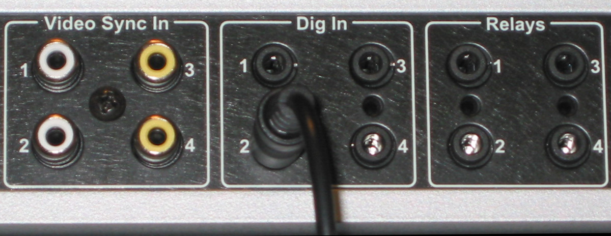
Note that all of the Video Sync inputs and
the Digital Inputs become highlighted in green.
Select the top-most Video Sync port.
|
|
|
|
You will get the menu at the right. Use the
default selection of "High when On" (meaning that when the Domain
3000 see a high signal on this input, it will assume the DVD player is
on).
Click OK.
|

|
|
After clicking OK, you will have added all
the wires necessary to the DVD player.
Click on the IR Control port of the Denon
AV surround receiver. Connect it to IR Out Port 3 of the Domain 3000.
You should end up with the schematic shown
below.
Now the Ubiquity software running in the Domain
3000 knows a path exists from the DVD player to the Living room TV and
speakers and it knows how to control all the components in the path. Therefore,
it can create a graphical user interface to control the DVD player.
|
|
|
Open the
Browser GUI
Close the Schematic
menu by clicking the "Done" button.
Select "File", "Open browser
GUI" from the dropdown menus in the upper left.
This will open the Browser GUI pointing to
the simulator (if you are working off line) or to the Domain Controller
(if you are connected to one).
|
|
|
Click in the Living room to open the Room
menu. |
|
|
Open
the Entertainment Browser GUI
Click on the Entertainment icon to open the
Browser GUI Entertainment menu. |
|
|
You will get a display like the one at the
right. You are looking at the entertainment in the "Living room".
It has buttons to play "Audio Video"
sources at the top left and to play "Audio" only sources at
the middle left.
It populates the buttons based on which AV
sources can get to the projector TV display and speakers.
Note that DVD player can be an audio-only
source when it plays CDs. If you select this button, the projector TV
will not turn on.
Click
on the DVD button.
You will have
to wait for the cycle accurate simulator to simulate setting up all of
the AV components in the path from the DVD source to the TV and speakers. |
|
|
Then you will get a display that looks like
this.
The white text at the top tells you that you
are looking at the entertainment equipment in the Living room and that
the Living room DVD is now playing.
By default, the transport menu will be shown.
The buttons of the transport menu are identical to the buttons on the
Destiny remote control. The actions assigned to each button is defined
in the Device Description File of the source that is playing at this point
in time (in our case, the DVD player).
|
|
Wire the PVR
Return to the Design Module.
Open the Schematic by clicking in the room.
Add the following wires to the PVR.
From the "Out 1:
Component" port of the PVR to the "Video 2: Component"
assignable input of the Denon. From the "Out 1:
Line stereo RCA" port of the PVR to the "DBS: Line stereo RCA"
input of the Denon. From "IR Out Port
2" of the Domain 3000 to the "IR Control" port of the PVR. From "Power Sync"
of the PVR to the "Video Sync Input 2" port of the Domain 3000.
The schematic should look like the one below.
Note that the Ubiquity software now knows
how to set up a path from the PVR to the Living room projector TV and
speakers.
|
|
|
See
the PVR on the Entertainment Browser GUI
You must re-generate the Entertainment Browser
GUI menu to update the menu with the PVR that was just added to the Design
Module.
Click on the Entertainment icon as shown at
the right.
|
|
|
You should get the menu at the right.
Note that the PVR button has been added to
the menu, but the DVD is still playing.
Click the PVR button, if you like, to see
the controls for it.
|
|
Control
the Dropdown Screen or Plasma Lift
Up until this point, we have assumed that
the projector screen is a fixed one (or that it was controlled by some
other component). However, the Domain Controller does an excellent job
of controlling dropdown screens and plasma lifts.
Every AV component can activate a relay or
a voltage trigger when it turns on. To get access to the relay, we need
to bring up the "Info" menu for the Living room projector TV.
Click on the word "edit" at the
top left of the component (or anywhere in the green area of the title
of the Living room TV). However, do not click on the far right on the
"X" as that is where you would click to delete the component.
|
|
The Info Menu
After clicking on the name of the AV component
in the schematic menu, you should get a menu like the one at the right.
Name and
Display Name
Here you see the name and display name of
the device. You can change them, if you want.
Mfg, Model, Device
Description File (DDF)
This tells you the name of the manufacturer
and model of this AV component. It also tells you the Device Description
file that is being used. This file could have come from the Destiny Library
or the User Library. However, at present, it is
part of this project and may be different than the ones you have in your
library if your library was changed after adding this description
file to this project.
|

|
Edit
this Device Description File
You can Edit the Device Description File -
to add to or change the IR or serial commands or to change the functionality
of the buttons of the remote control (as we will see shortly). When you
click this button, the Device Description Wizard will open to this AV
component inside your project. When you finished with the Device Description
Wizard, it will change the device description of the AV component in this
project and offer to save the changes to your User Library, as well.
Use
a different Device Description File
You may already have a different Device Description
File in your User Library or in the Destiny Library that you would like
to use. Click the "Use a different Device Description File button,
and it will let you browse to the Device Description File you
want. It will also try to preserve the wires that are connected to the
device in your project as best as it can.
Turn
the Power on and off as Needed
There's a check box to turn the power on and
off as needed. If you wanted to just leave the AV component on all of
the time, uncheck this check box.
Energize a Relay
At the bottom, there is a checkbox labeled
"Energize a relay (to turn on)". If this checkbox is checked,
then when the Domain Controller turns this AV component on, it will also
energize a relay (the relay to energize is determined on the schematic
menu as shown below). When the Domain Controller turns this AV component
off, it will de-energize the relay .
|
|
Check the box labeled "Energize a relay
(to turn on)".
It should now look like the menu at the right.
Click OK. |
|
|
At this point a new line will be added to
the bottom of the Living room TV component labeled "Energize a relay".
Now you need to associate this with an actual
relay. To do that, click on the "Energize a relay" port to select
it.
You will get the schematic shown below where
the possible relays and 12V triggers that can be used to power the dropdown
screen become highlighted in green. |
|
|
|
|
Click on the Domain 3000 port labeled "12V
Triggers Unit, Relay 1" to assign that voltage trigger to the projector
TV. Therefore, whenever the Domain 3000 sends a
command to the projector TV to turn it on, the Domain 3000 will also energize
"12V trig #1" of the Domain 3000 to go high. The 12V
trigger will stay high until the Domain 3000 sends a command to the projector
TV to turn it off. At that point, it will de-energize the 12V trigger,
too.
The schematic for this is shown below.
|
|
|
|
o |
Test
the AV Signal Paths and IR Emitters
Use the handheld remote controls that
came with each AV component to set up a path from an AV source
(such as a DVD player or Personal Video Recorder) to your TV and speakers.
Doing this by hand will insure that the AV components are wired together
properly and that the mechanical power switches of each AV component is
in the correct position for IR control. Turn all components off using the remote control
that came with each AV component. Open the Entertainment
menu of the Browser GUI by doing the following:
In Find My Destiny,
make sure the Domain 3000 has been selected in the right side of the application
by clicking on the name of the Domain 3000. Click the button
on the left labeled "Launch Browser GUI" (wait for it to appear). Click inside the
blue rectangle and the "Room Menu" will appear. Click on the entertainment
icon (it looks like a movie file that evolves into a music cleft). The Entertainment menu will open.
On
the left side of the Entertainment menu you should see a button for each
AV source. In addition, each button will be under one of the following
headings: "Audio Video", "Audio", or "Video"
- representing the capabilities of the source. If
any source does not appear, or if it appears in the wrong category, then
you have not created an AV path from the source to the display or speakers.
You need to go back to the Schematic menu of the Design Module and complete
the AV paths. Note that only AV sources such as DVD players, MP3 players,
Tuners, etc have buttons assigned to them. AV Surround Processors, Switches,
Video Processors, Speakers, and TVs (a.k.a. displays and projectors) do
not get buttons assigned to them. If you want a button assigned to a TV,
then, in the Device Description File for that TV, it must have a Tuner
as an "Internal component". Also, pay
particular attention to the type of video signal. The software
knows that a composite signal from a source to an AV Surround Processor
cannot be converted to an S-Video signal from the AV Surround Processor
to the TV unless the AV Surround Processor supports "Transcoding".
Click one of the source buttons on the left side
of the Entertainment menu. If the entire path sets up properly, and the source
is playing on the TV and speakers, and you can control the source using
the transport, menu, and/or keypad commands, and you can control the volume,
then you are done with that source. Go back to step #4 and select a different
source. If the entire path does not set up properly go to step 6. Identify
which AV component in the path that did not turn on or set up properly.
The possible problems are listed below. Steps 8
through 13 will help you determine the actual problem.
The actual path that the AV signals need to take
(from the source that is playing to the TV and speakers) is different
than the path that has been configured into the software. See #8 below
to eliminate this as a possible problem. The IR emitters are not working or are not pasted
onto the AV component in the correct location, OR, the IR emitters are
not plugged into the proper port on the Domain 3000 (as configured into
the software). See
#9 below to eliminate this as a possible problem. The Device Description File of one of the AV component
is the wrong Device Description File for that component, OR, the IR codes
in the Device Description File for that component are incorrect. See #10
below to eliminate this as a possible problem. The IR codes in the Device Description File for
that component are not associated with the Destiny commands properly.
See #11 below to eliminate this as a possible problem. If the AV component does not have discrete power
on/off commands, then the "Power Sync" signal may not be working
properly. See #12 below to eliminate this as a possible problem. The "post delay" times in the Device
Description File are incorrect. There was not enough "dead time"
between sending the command to it to turn it on and sending the command
to it to select one of its inputs. See #13 below to eliminate this as
a possible problem.
Use the steps below to
eliminate each of the problems above. On the Entertainment menu, click on the "Advanced"
button (located under the volume and channel buttons). This button is
only available after a source has been turned on. On the left hand side
is the list of AV components that Ubiquity thinks it should control to
set up the path. If the AV component that is not working is not listed,
then the problem is "a" above. You need to go back to the Schematic
menu of the Design Module and set up the AV paths properly. To see how
the software thinks you have set up the path, open Check
My Destiny, expand the "Entertainment" section (it will
be 2nd from the bottom). Expand "Theater room", expand "Theater",
and click on "Show last 20 cmds". You may have to resize the
window to make it easier to view. It will list the commands it took to
set up the path from the source to the display and/or speakers. At this point, you have identified that the software
tried to set up the correct path from the source to the display and/or
speakers, and you have identified one or more AV components that are not
being controlled properly. We need to determine if an IR signal is getting
to the AV component. On the Advanced Entertainment Menu, select the component
on the left that is not working properly. A field of button will appear
on the right. Find the "Power On" button. Click it. If the power
turns on, you have eliminated "b" and "c". If not,
check your wiring or substitute a Blinking IR emitter and see that it
blinks. Note that just because it blinks, does not mean that IR is being
transmitted. We once ran across a set of blinkers where the emitter blinked,
but the IR was not being sent. Also check that the IR blinker is plugged
into the proper port of the Domain Controller (as configured into the
software). Finally, make sure that it is pointing at the IR receiver of
the AV component. Place a large piece of cardboard in front of the AV
component. Make a small hole in it and place the hole in front of the
IR emitter. Use the remote control that came with the AV component to
turn the component on and off. If you succeed, then the IR emitter is
in the correct place. At this point, you have working IR emitters, and
if the IR commands on the Advanced Entertainment menu control the AV component
properly, you have eliminated "d", so please continue to #11.
Otherwise, one or more of the IR codes is incorrect. Open the Info
menu of the AV component by clicking on the name of the AV component
on the Schematic menu of the Design Module as described above. Make sure
you have the right Device Description File (i.e., the "File name"
is the one you have been working with). If not, get the correct file by
clicking the "Use a Different Device Description File" button.
If you are using the correct file but the IR commands on the Advanced
Entertainment menu are not working properly, then the IR codes themselves
must be incorrect. Open the Device Description File using the "Edit
this Device Description File" button and re-learn and test the IR
codes. At this point, you have working IR codes. However,
they may not be associated with the proper Destiny Commands. Open the
Info menu
of the AV component by clicking on the name of the AV component on the
Schematic menu of the Design Module as described above. Open the Device
Description File using the "Edit this Device Description File"
button. Go to the "IR Associate" page. Make sure that the appropriate
Destiny "power (on/off)" commands have been associated with
IR codes. If the AV components has multiple selectable inputs (eg. the
way an AV surround receiver or TV would have multiple inputs to select
from), then make sure that all Destiny "select <input>"
commands have also been associated with IR commands. If you are having
trouble with the transport, menu or keypad button on the Entertainment
GUI (not the Advanced Entertainment GUI), refer to those pages of the
Device Description Wizard and make sure that the proper IR codes have
been associated with them, as well. At
this point, all of the IR codes work properly. Therefore, if the AV component
did not turn on, it is because of a problem with the "Power Sync"
status connection. If the AV component does not have discrete power on
and power off commands (that is, if the AV component only has a power
toggle IR command) then the AV component should have a power status connection
to the Domain Controller. Make sure this connection has been connected
and that it is connected to the proper input on the Domain Controller.
Open "Check My Destiny". Expand the Domain Controller. Expand
the "Video Sync Inputs" or "Video / Digital Inputs"
(as appropriate). Expand the "List of Commands". Use the remote
control that came with the AV component to turn the power on and off.
If the change in status does not appear on "Check My Destiny",
then there is still something wrong with the connection. Note
that some AV sources (especially satellite receivers and cable set top
boxes) that transmit a progressive or digital video signal will not output
Composite or S-Video at the same time because Composite and S-Video
are inherently interlaced signals. Therefore, you cannot use the Composite
signal for Video Sync if you are using a Progressive or digital signal
out of the AV component. Also note that on a few AV components (such as
the EchoStar Dish 501 PVR) the Composite output
signal is disabled when the S-Video output is connected to another
AV component. This means that the Composite output cannot be used for
Video Sync. Finally, most Satellite receivers and set top boxes have the
same "On" current as their "Off" current. Therefore,
a current sensor may not be able to tell the difference between the on
and off states. Usually, you can use a light sensor such as Niles
Audio Light Sensor. These are pretty expensive. Therefore, your other
2 choices are to disable controlling power or live with the software toggling
the power. To disable controlling power, go to the "Info menu"
of the AV component in the Design Module and uncheck "Turn power
on and off as needed" (note that this means the Domain Controller
will not try to turn the AV component on or off, at all). Alternatively,
you can let the destiny software toggle the power on and off. It does
a good job of maintaining state, but, more importantly, if it does get
out of sync you can press the source button on the remote again and it
will send the toggle power command a second time. Note that this only
works if there is only one AV component in the path without discrete commands
or power sensing. Finally,
the only problem left with setting up a component in the path is that
the proper input of the AV component was not selected because the "post
delay" time for Power On was too short. To test the post delay times,
open the Info
menu of the AV component by clicking on the name of the AV component
on the Schematic menu of the Design Module as described above. Open the
Device Description File using the "Edit this Device Description File"
button. Go to the "IR Post Delay Test" page, and run the tests
for "Power (on)" followed by "select <input>".
It is likely that you will need to increase the Power on post delay. If the problem is not fixed please, please contact us. |