Run the Design Module
Click "Start", "Programs", "Destiny Networks", "Ubiquity 3.1", "Design Module"
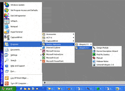
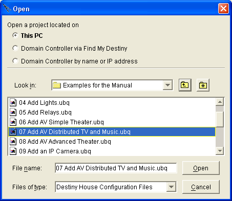
Open the Project: 07 Add AV Distributed TV and Music.ubq
To open the project, select "File", "Open Config/Project"
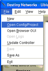
You will get the following menu.
Navigate to "C:\Program Files\Destiny Networks \Ubiquity \Ubiquity3.1 \Examples \Examples for the Manual"
Click the "Open" button
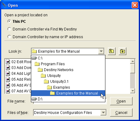
You will get the following menu.
Click on "07 Add AV Distributed TV and Music.ubq".
The project will open. Go to the next step of adding the lighting system.
Modulate the zone 2 output of an AV surround receiver to a single room
Select the AV Entertainment layer of the Design Module.

Click anywhere in the room in which you plan to add AV equipment (AV Equipment is location independent).
You will get the schematic that we ended up with at the end of the previous example (as shown below).
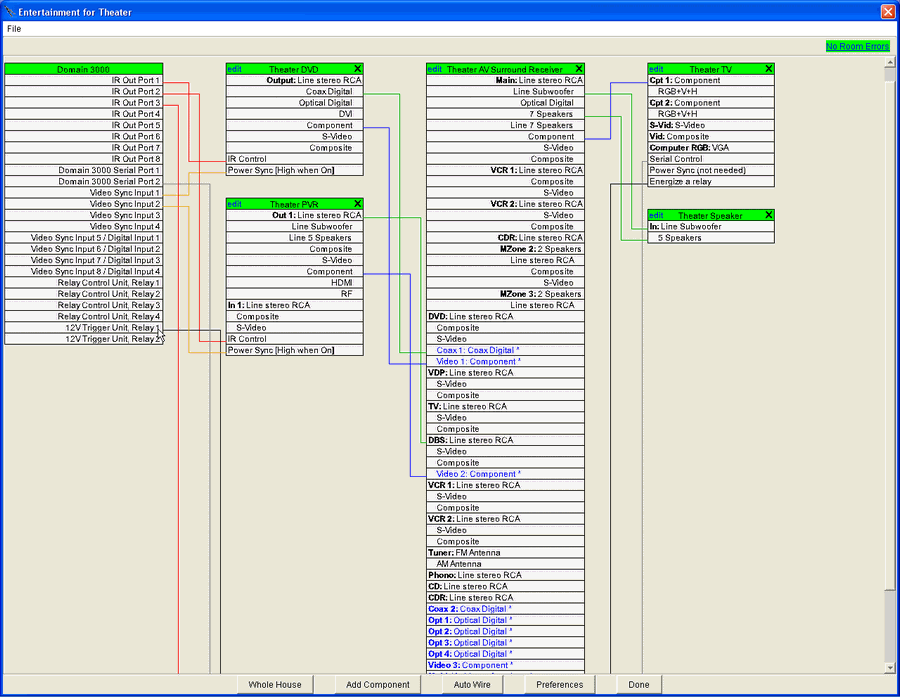
Add an AV to RF modulator
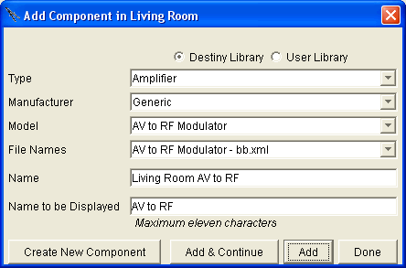
Click the "Add Component" button in the menu above
For "Type" use the dropdown menu to select "Amplifier".
For "Manufacturer" select "Generic".
For "Model" select "AV to RF Modulator".
Change the name to Living Room AV to RF
Click "Add"
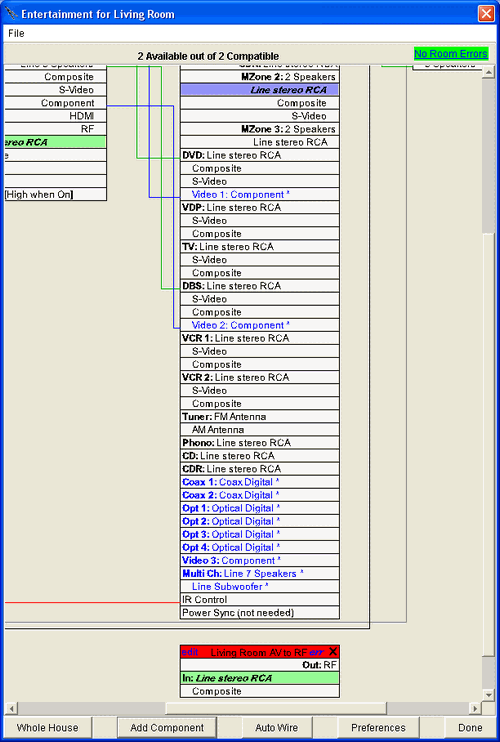
Select the "MZone 2: Line stereo RCA" output of the AV surround receiver and connect it to the "In: Line stereo RCA" of the modulator.
Do the same with the "MZone 2: Composite" output.
Click "Done" to close the schematic menu.
Add the Sharp Aquos LC-13E1U 13" LCD TV
Click anywhere in the Master bedroom to get the menu of the schematic of entertainment equipment in the Guest bedroom.
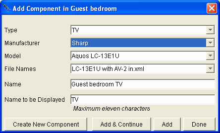
For "Type" use the dropdown menu to select "TV" (or press the "T" key with this field highlighted).
For "Manufacturer" select "Sharp".
For "Model" select "Aquos LC-13E1U AV-2 in".
Click "Add"
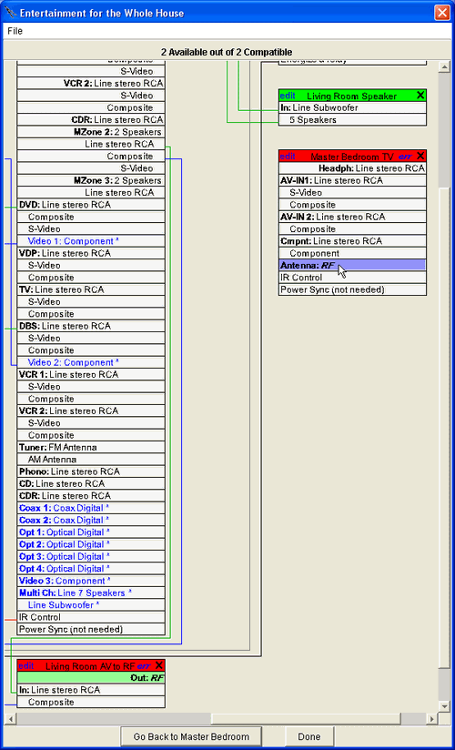
After adding the Sharp TV, select its "Antenna: RF" input.
Connect the wire to the "Out: RF" output of the modulator.
Add IR control to the Sharp TV.
Open the Device Description File of the Sharp TV
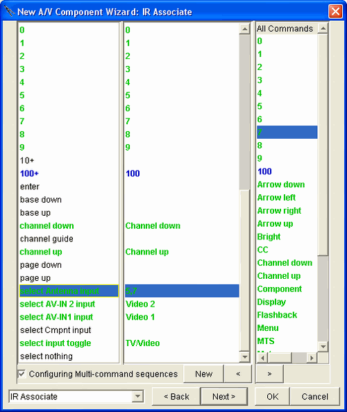
Go to the "IR Associate" page.
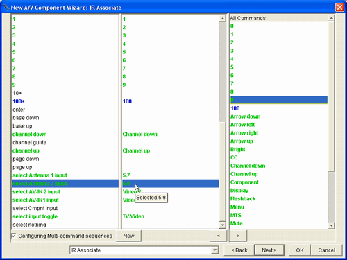
Enable "Configuring Multi-command sequences".
Select the "select Antenna input" Destiny command on the left.
Associate the channel number of the modulator with selecting the RF input (in our example, the RF modulator uses channel 57. With other TVs you may need an "enter" command, also.
Click OK and say "Yes" to saving it to your user library.
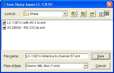
Change the File name to something like what you see at the right.
This is important because it makes this TV a unique file. Therefore, you can add additional TVs of the same type using the previous file type such that they will not go to channel 57 when the antenna input is selected.
Click Save.
Go back to the schematic of the Living room and from the sources to the AV surround receiver. This is important because the AV surround receiver does not do down converting. Therefore, the video path will not exist to the Master bedroom TV until there is a composite path from the sources to the AV surround receiver.
Open the Entertainment Browser GUI in the Master bedroom and you will see the sources from the Living room.
Open Check My Destiny and see the TV enter channel 57 when any of the sources are played.
You are done.
Modulate the zone 2 output of an AV surround receiver to a multiple rooms
To send the modulated signal to more than one room, modify the "AV to RF Modulator" of the previous example such that it has multiple RF outputs - one for each TV and/or set of speakers that you want the signal to go to.
Add the TVs and/or sets of speakers to the desired rooms. Make sure to use the Device Description File from you User Library - the one with the "select Antenna input" that selects the channel of the modulator.
Wire the RF signals from the modulator to each TVs and/or sets of speakers.
Add the control wires.
You're done.
Modulate 2 or more sources to multiple rooms
This example builds on the previous two examples. In this case, we need to modify the Device Description File of each TV such that it has 2 or more RF inputs - one RF input for each source. These additional RF inputs do not really exist, but we need them so that the "select Antenna input" commands can enter the channel number of the modulator for the source we want to watch.
For this example, we will start from scratch and add the following AV components:
|
Type |
Manufacturer |
Model |
Device Description File |
|
DVD |
Samsung |
DVD-P231 |
DVD-P231 play for power on |
|
PVR |
DirecTV |
HD DVR |
HD DVR |
|
Amplifier |
Generic |
AV to RF Modulator |
AV to RF Modulator 1:2 |
|
Amplifier |
Generic |
AV to RF Modulator |
AV to RF Modulator 1:2 |
|
TV |
Sharp |
Aquos LC-13E1U |
Ant to chan 57 |
Next, we modify the Device Description File of the TV such that it has two antenna inputs and each has a multi-sequence command associated with it to select the channel of the appropriate modulator.
We add a second TV using this Device Description File to the Master bedroom.
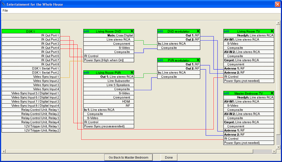
Finally, we wire the sources to the modulators and the modulators to both TVs such that antenna 1 of both TVs is selecting the DVD source and antenna 2 is selecting the PVR source as shown below.
Open the Entertainment Browser GUI and Check My Destiny and try it. It really works nicely.