GE Interlogix (Caddx) Security Systems

GE Interlogix manufacturers the NX-8E security system (formerly known by the Caddx brand name). It interfaces to the Domain Controller via RS-232, as does the NX-8 with the NX-584 option.

This feature is now supported on the Domain 3000 in the 3.0 release for an additional software charge. Please email support@destinynetworks.com to receive the key to turn on this layer. This system must be connected directly to a Domain 3000 serial port. It is not supported on the Lantronix, Global Cache GC-100, or on the Domain 2000 in the 3.2 release.

Overview:


Security System Architecture

GE Interlogix NX-8E OR NX-8 with the NX-584

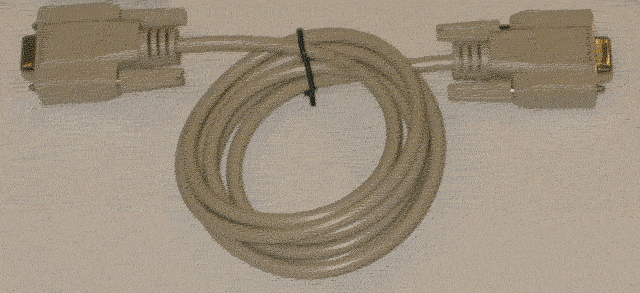
In the picture at the right the security system is connected to the Domain Controller via RS-232 with a straight through cable

.


Wiring the Domain 3000 for the NX-8 with the NX-584

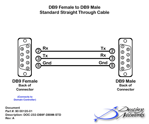
For the NX-8 with the NX-584 (but not the NX-8E - see below), the serial cable is a standard straight through RS-232 cable.


Wiring the Domain 3000 for the NX-8E

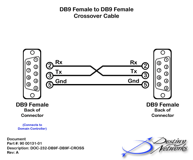
For the NX-8E (but not the NX-8 with the NX-584 - see above), the serial cable is a female-to-female crossover RS-232 cable.


Program the Security System

All programming is done from the LCD keypad of the security system.

The factory default for the Master code is [1]-[2]-[3]-[4] when using a 4-digit code or [1]-[2]-[3]-[4]-[5]-[6] for a 6-digit code. The factory default for the "Go To Program" code is [9]-[7]-[1]-[3] for a 4-digit code or [9]-[7]-[1]-[3]-[0]-[0] for a 6-digit code.

To enter the Program Mode, press * 8. At this time, the five function LEDs (Stay, Chime, Exit, Bypass, & Cancel) will begin to flash. Next, enter the "Go To Program Code" (FACTORY DEFAULT IS [9]-[7]-[1]-[3] for a 4-digit code or [9]-[7]-[1]-[3]-[0]-[0] for a 6-digit code. If the "Go To Program Code" is valid, the "Service" LED will flash and the five function LEDs will illuminate steady. You are now in the Program Mode and ready to select the module to program.

Please choose the model to setup:


NX-8/6/4 with NX584

Location

Action

LCD Display

NX-8/6/4 with NX584


Enter Programming Mode

System Ready Type code to arm

* 8   9 7 1 3

or

* 8   9 7 1 3 0 0


Select the controller

Enter the device address then #

7 2 #

0

Use ASCII

Enter location, then #

0#


Turn on bit 1

Loc# 0  Seg# 1

- - - - - - - -

1


Exit this location

Loc# 2  Seg# 1

1 - - - - - - -

*

1

Baud Rate 9600

Enter location, then #

1 #


Turn on bit 4 for 9600 or 10 for Automatic

Loc# 1  Seg# 1

10 (A)

4 or 10


Exit this location

Loc# 1  Seg# 1

10 (A)

* * * * * *

(until location is exited)

2

Transitions: All locations can be left in their default disabled state

3

Command / Request

Enter location, then #

3#


Turn on bits 2,4,5,6,7,8

Loc# 3  Seg# 1

- - - - - - - -

2 4 5 6 7 8


Go to segment 2

Loc# 3  Seg# 1

- 2 - 4 5 6 7 8

*


Turn on bits 1

Loc# 3  Seg# 2

- - - - - - - -

1


Go to segment 3

Loc# 2  Seg# 2

1 - - - - - - -

*


Turn on bits 5,6,7,8

Loc# 2  Seg# 3

- - - - - - - -

5 6 7 8


Go to segment 4

Loc# 2  Seg# 3

- - - - 5 6 7 8

*


Turn on bits 5,6,7,8

Loc# 2  Seg# 4

- - - - - - - -

5 6 7 8


Exit this location

Loc# 2  Seg# 4

- - - - 5 6 7 8

*


Exit device setup

Enter location, then # (3)

Press "Exit" button


Exit programming


Press "Exit" button

 
NX-8E

Location

Action

LCD Display

NX-8E


Enter Programming Mode

System Ready Type code to arm

* 8   9 7 1 3

or

* 8   9 7 1 3 0 0


Select the controller

Enter the device address then #

0 #

207

Enable the Serial Port

Enter location, then #

2 0 7 #


Turn on bit 1

Loc# 207  Seg# 1

- - - - - - - -

1


Exit this location

Loc# 207  Seg# 1

1 - - - - - - -

*

209

Use ASCII

Enter location, then #

2 0 9 #


Turn on bit 1

Loc# 209  Seg# 1

- - - - - - - -

1


Exit this location

Loc# 209  Seg# 1

1 - - - - - - -

*

208

Baud Rate 9600

Enter location, then #

2 0 8 #


Turn on bit 4 for 9600 or 10 for Automatic

Loc# 208  Seg# 1

10 (A)

2


Exit this location

Loc# 208  Seg# 1

10 (A)

*


210

Transitions: All locations can be left in their default disabled state

211

Command / Request

Enter location, then #

2 1 1 #


Turn on bits 2,4,5,6,7,8

Loc# 211  Seg# 1

- - - - - - - -

2 4 5 6 7 8


Go to segment 2

Loc# 211  Seg# 1

- 2 - 4 5 6 7 8

*


Turn on bits 1

Loc# 211  Seg# 2

- - - - - - - -

1


Go to segment 3

Loc# 211  Seg# 2

1 - - - - - - -

*


Go to segment 4

Loc# 211  Seg# 3

- - - - - - - -

*


Turn on bits 5,6,7,8

Loc# 211  Seg# 4

- - - - - - - -

5 6 7 8


Exit this location

Loc# 211  Seg# 4

- - - - 5 6 7 8

*


Exit Device Setup

Enter location, then # (3)

Press "Exit" button


Exit Programming


Press "Exit" button


Summary of Programming NX584 / 8E
Location NA / 207: Enable Serial Port

For the NX-8E, you must enable the serial port. This step is not necessary for the NX584.

Location 0 / 209: ASCII / Binary

Select it to ASCII mode.

Location 1 / 208: Baud Rate

Use its default baud rate of 9600 Baud.

Location 2 / 210: Transitions

Disable all options at this location.


Location 3 / 211: Command / Request Enables

Enable the options highlighted in yellow at the right.

Location 4 / 212: LCD Keypad Address

Do not change factory defaults.

Location 3 / 211

Segment 1Data

Supported Request / Command

1

disabled (Reserved)

2

Interface Configuration Request

3

disabled (Reserved)

4

Zone Name Request

5

Zone Status Request

6

Zones Snapshot Request

7

Partition Status Request

8

Partitions Snapshot Request

Segment 2 Data


1

System Status Request

2

disabled (Send X.10 Message)

3

disabled (Log Event Request)

4

disabled (Send Keypad Text Message)

5

disabled (Keypad Terminal Mode Request)

6-8

disabled (Reserved)

Segment 3 Data


1

disabled

2

disabled

3

disabled

4

disabled

5

disabled

6

disabled

7

disabled

8

disabled

Segment 4 Data


1

disabled

2

disabled

3

disabled

4

disabled

5

Primary Keypad Function with PIN

6

Primary Keypad Function without PIN

7

Secondary Keypad Function

8

Zone Bypass Toggle


Test the serial port of the Security System

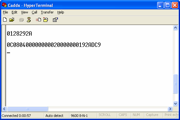
Connect the Security System to your PC with a  commercially bought RS-232 cable. Open up Hyper Terminal at 9600 baud.  The full set up is: 9600 baud, 8, none, 1, none. Then, in the Hyper Terminal settings menu append line feeds both ways, and echo typed characters. Type 0128292A and enter. You should get the reply at the right or some other similar reply. Note that changing the connector for the Domain Controller to your PC or power cycling the security system tends to get the security system 's serial connection in a funny state, so it is best to try typing the numbers a couple of times.


Connect the cable

If you have the NX-8 with the NX-584 board, connect a straight through RS-232 cable from the Domain Controller to the security system.

If you have the NX-8E, connect a crossover cable from the cable adaptor of the NX-8E to the Domain Controller (you will often also need a gender changer). Note that the P-0003 cable should be connected to the serial header so that its connector is plugged into the NX8E board with the Red Edge of the ribbon cable closest to the bottom of the board.


Software

To add the NX-8E (or NX-8 with the NX-584) option, start by selecting the Security Systems layer of the Design Module.


Add the Security System

Click in the location in the room in which you want to add the security system.


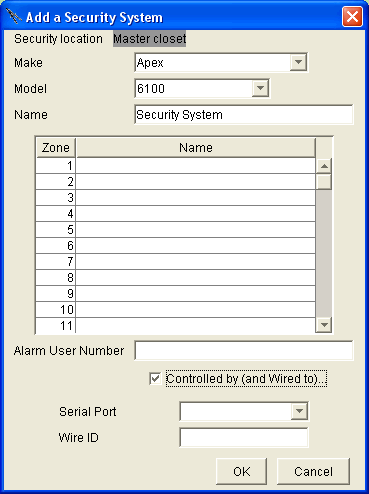
At first you will get a menu like the one at the right.

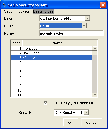
Make the changes listed below.


Make: select GE Interlogix Caddx.

Model: select either the "NX-8E" or the "NX-8 + NX-584".

Type the zone names to the right of the zone number that they have been wired to (that is, enter the actual zones that have been wired to the security panel).

Serial port: select any available serial port.

Note the serial set up of the NX-8E security system is 9600 baud, no parity, 8 bits, 1 stop bit, no flow control. The Ubiquity software knows this. You do not need to do anything to set it up.

Click OK, and you are done setting up the Ubiquity software.


After entering all the data, save the project to the Domain Controller and back it up on your computer and re-connect to the Domain Controller (silver border on the Design Module).

 Then, re-start the security system (power cycle it).


View the Security System on the Browser GUI

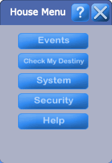
Open the Browser GUI and click outside of all rooms to bring up the House menu.

Click on the "Security" button (the 2nd from the bottom on the right).


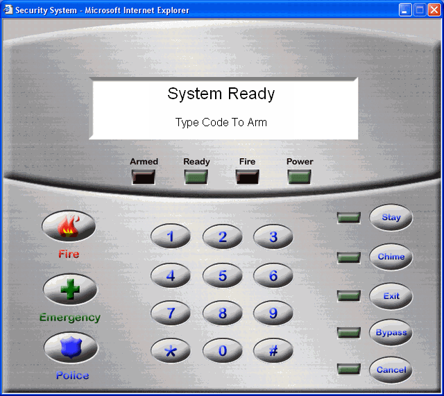
You will get a graphical image of a real security panel for this security system as show at the right.


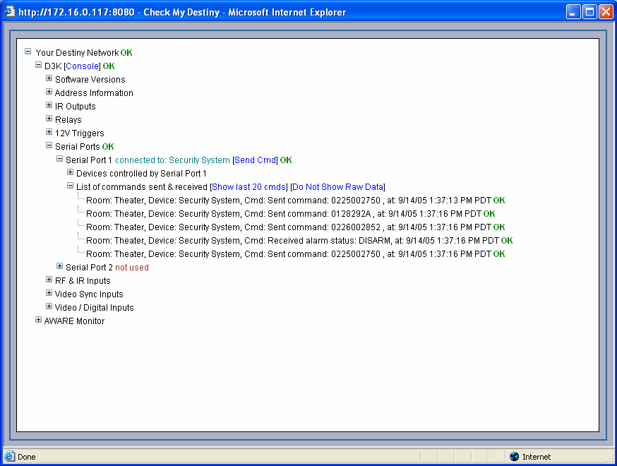
If you bring up Check My Destiny, it should look like the display below (after turning on "Show Raw Data").